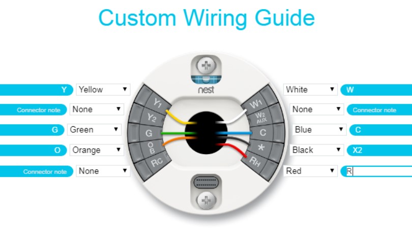
A Nest Wiring Diagram is a graphical representation of how wires and cables are connected to one another in order to form a functional electrical system. The Nest Wiring Diagram was created by German Electrical engineer Signfried Wundt in 1938 to aid an assembly worker who was attempting to install a wiring system for a new radio-controlled car. Although the installation went smoothly the following day, the next two weeks the car would not start at all. The wires were not properly connected or the spacing was too small for the wires to lie flat against the car’s framework.
To resolve this problem Wundt drew the wiring diagram on a large piece of graph paper and labeled it “Nest Wiring diagram v2”. This second version has wirings – tiny circles – instead of dots. The change in terminology from dot-to-dots helped Wundt make his wiring diagrams more easily understood by others. In later years this method became standard in many industries including electronics and computer manufacturing. With computers becoming so widely used in many other industries such as medicine, the Nest Wiring Diagram became almost a common standard. Today, it is still used extensively in electrical engineering units around the world.
The first thing to notice when comparing Nest Wiring Diagrams from different eras is that back then the wires were always run in the same direction – from left to right. Nowadays, wiring can be done any way you wish as long as the wiring diagram is followed. It is possible to have a completely different wiring diagram if two different components need to be connected. The Nest Wiring Diagram shows the path of each wire while also showing that the component is on what wire. For example, when connecting a speaker to the computer the speaker will be connected on the left and the computer on the right. If two components need to be connected then the wiring diagram is turned right so that all of the components are on the left side.
When the wires from different components are run together they form what is called a path. This is where the computer and the speaker are located. A short circuit exists between the speaker’s positive and negative terminals and the wires form a complete loop. This short circuit is what causes the current to flow from the speakers to the computer.
The most common way that a short circuit is created in electronic equipment is when two components come into contact with each other at the same time. This can happen because a piece of insulation is missing between the two points. This creates a short in the wiring. It is important to make sure that the insulation is present or else the wiring may not touch and create a short. When there are wirings in electronic components, they are usually referred to as shorting elements.
Since nests are made to avoid shorts between component’s it is necessary to place equipment near the wirings. This will ensure that all of the components inside the enclosure are properly insulated. The best way to install the nest wirings is by drilling tiny holes into an area and then installing the nest wires in their holes. This allows the wires to be connected between all parts of the enclosure without gaps. This is one of the main reasons why they are becoming more popular among companies because it saves time and money in repairs.
