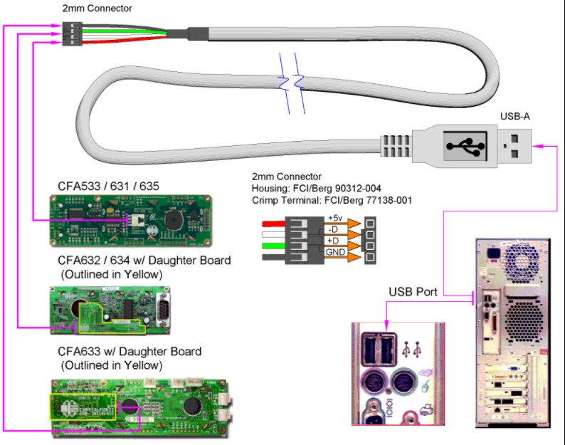
A USB Wiring Diagram displays the information needed to properly configure a USB port for a particular device. There are four major types of USB ports available on computers today. USB port 1 is the smallest type of USB connection available, used to connect electronic devices such as digital cameras, video recorders, and printers to personal computers. The other three major types of USB ports are USB ports 2, USB ports 3, and USB ports 4. Each USB port has its own unique set of pins that are used to power and communicate with a USB device.
A USB Wiring Diagram will help a computer user to identify which port has connectivity with which device. If you connect two devices together using different USB connections and then try to power them both with the same type-a USB power adapter, for instance, you may get this response from the device: no device is powered by USB. This is because in this particular case, the power adapter is trying to use a USB port that is already attached to another device that is using a different type-a USB port. Hence, the computer user needs to connect one USB port to a USB device and the other USB port to a USB device.

To resolve this issue, the USB Wiring Diagram will show a clear picture of the electrical connection between the USB port and the device being connected. The four types of USB ports are USB port 1, USB ports 2, USB ports 3 and USB ports 4. The USB Wiring Diagram has a special drawing of a USB connector that clearly shows the difference between the various USB connections. For convenience, the color code is also indicated on the pinout diagram.
When it comes to the USB-Wiring Diagram, you can see that the first USB port has a positive wire attached to its corresponding positive terminal and the other USB port has a negative wire connected to its corresponding negative terminal. Thus, the USB connector is designed like a mini-conductor. This is the reason why there is a small gap between the two USB ports. You can see that the USB connector is designed in such a way so that only one wire is required to be connected between USB ports. This is why some external hardware devices can only be connected to a USB port while some USB devices can only be connected to a USB port.
Since the USB connector is very small, you can connect multiple USB devices onto one single USB port. As a result, the size of a USB Wiring Diagram pinout diagram also becomes smaller. This makes it easier for computer users to keep track of the USB cables. If you are still not able to find a proper USB pinout diagram, you can search online for more information about USB Wiring Diagram pinout diagrams. Once you get more information about the USB connector, you will be able to find the right kind of cable needed for the USB port and the right USB cable to use for its connection. You will then be able to find a USB connector pinout diagram that suits your computer hardware.
The USB connector is basically an electro-optical data transceiver. It transmits the USB power signal, and a type-I connector on the other end, which carries the data signal. Hence, both the USB connector and the type-b connector carry the same data signal, which enables it to communicate with each other. The advantage of a USB connector is that it transmits the data as a parallel in both directions, which enables it to interface with a host computer.